
While setting up my local mbed development environment I came across one issue I could’t fix for some time – I couldn’t manage to use printf() to display debug messages on my computers terminal emulator from an external prototyping board.
Basic SWD / JTAG hardware setup
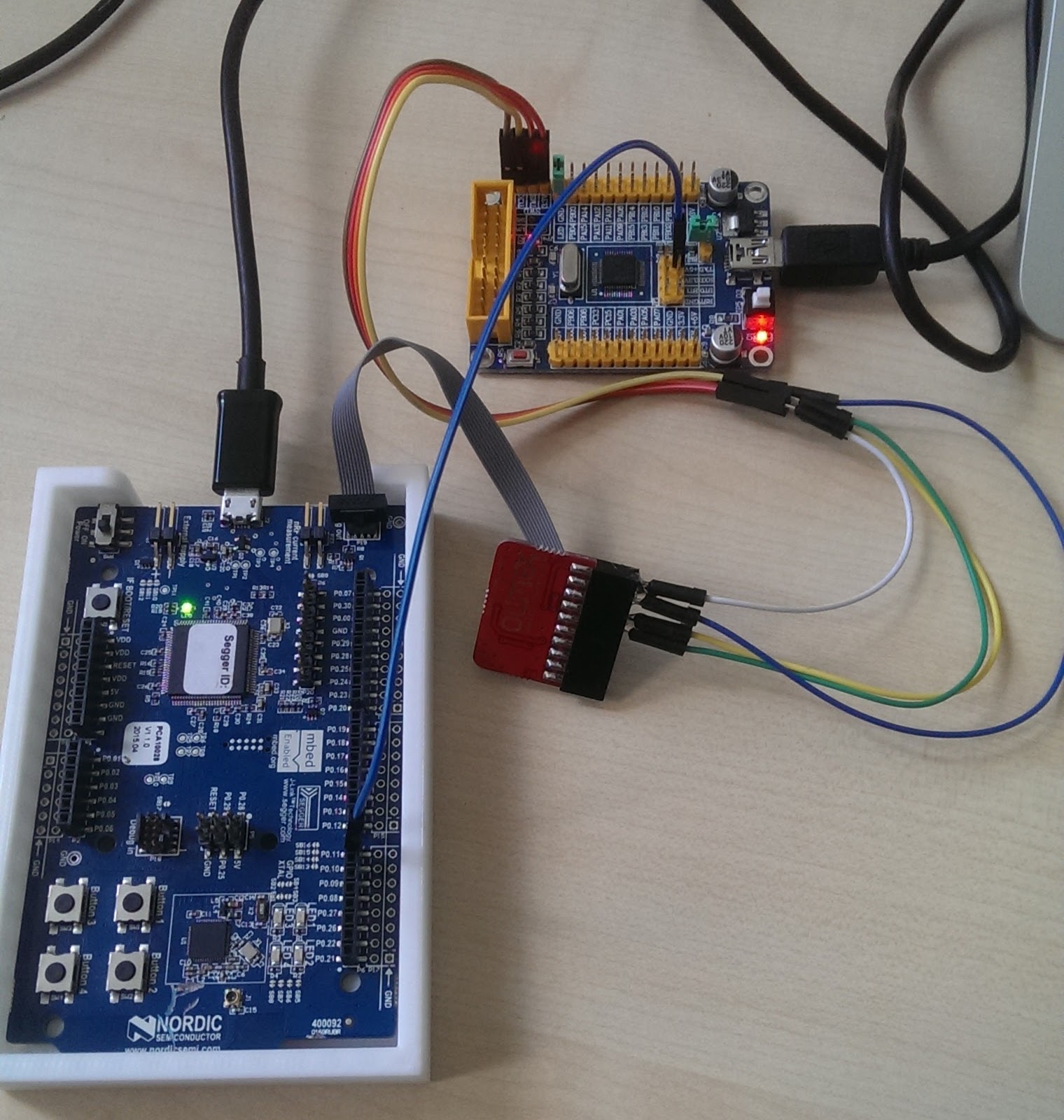
Programming and debugging of external boards (debugging in a sense of using JLINK / OpenOCD to use the debugging capabilities of embedded processors) was easy to setup by installing a 4 wire JTAG connection cable. I bought a JTAG adapter cable from Olimex which fits on the P19 0,05″ header and connected SWDIO, SWDCLK, GND and VCC to the external board. It’s crucial to understand that VCC is the external boards power supply that triggers the JTAG Interface to connect the external MCU, not the nrf51 on the development kit! As I figured out after I ordered the Olimex P20 supplies the SWD interface as well – so no need to go through this very rare 0,05″ header .

No UART over SWD
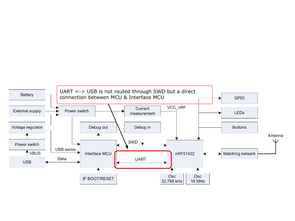
I assumed that I could use UART over SWD until I reviewed the DK’s user guide again which clearly shows that the onboard MCU’s UART is connected directly to the Interface MCU (see diagram below)
I raised a question in the mbed forum Is UART printf possible through SWD/JTAG? to confirm my theory and to get some best practises. Wim Huiskamp came back instantly and mentioned that I could use:
- SWO which would require additional three connections. Unfortunately it is not implemented on ARM Coretex M0 Cores such as the nrf51
- use a FTDI 232 based UART to USB serial adapter
UART routed through the DK’s nrf51!
I really liked the idea of using the FTDI 232 besides the fact that I would require an additional connection to the external board (TX -> RX) plus the FTDI. But hold on. Why not flashing a serial loopback program on the DK’s nrf51 and use the Interface MCU UART <-> USB bridge? So I just had to find the RX header pin (P0.19) on the Nordic DK and connect it to the external boards TX Pin, flash the compiled hex file and give it a try.
It worked out of the box and I could put a tick in the box to one of the mysteries I had been working on for so long.